
Converting from DC to DCC
When converting from DC, what wiring changes to I need to make? Perhaps None!
If your layout works well on DC, it MAY work well on DCC! The best way to find out is to test it:
Disconnect your power pack and substitute a DCC set - the Digitrax Super Chief is a favorite of Bruce's for this, as it beeps when it sees a short. Otherwise, connect a bulb across the rails so that you can see when the track voltage is on.
Conduct the "Quarter Test:" Place a quarter across the rails everywhere around the layout and assure that the DCC set sees the short and shuts off the power.
If your layout passes these criteria, you should be fine. If not, rework is indicated, rip out the wiring and start as if you were building new.
Building a new layout or rewiring
Here’s what I recommend for S or smaller gauge layouts (using a 8-amp or smaller booster):
The goal of this exercise is to provide a power drop to EVERY piece of track. I know that this may sound like overkill, but I’ve never seen a layout where this was done that had problems. Many that tried to shortcut this step do have problems. The extra time and a few dollars worth of wire are much less expensive than the frustration and time spent reworking a layout – especially after the scenery is in place!
Buy 20 AWG thermostat wire (home improvement stores sell it as twisted pair – two solid wires twisted loosely together). The last roll I bought was 500 feet of red and white for about $30. Any smaller (higher number) and the loss in the wire causes problems – any larger and it is difficult to connect to the track.
Buy enough house wire to run a loop around under your mainline plus about 20% for those gotchas that always happen. I recommend 12 AWG for runs in excess of 40 feet and 14 AWG for shorter runs. A small shelf layout (say under 20 feet long) could suffice with 16 AWG. A quick check is to take add all the dimensions of the edge of your layout and add 10%. If you have a U-shaped layout with dimensions of 10, 17, 8, 4, 4, 9, 6 and 4, just add them up (62) and add 10% - buy about 70 feet of each wire. Since I got red and white thermostat wire, I’d buy 70 feet of red and 70 feet of white house wire.
Now comes the question – how do I connect the track feeders (20 AWG wires) to the power bus (the house wires)? There are three methods – each with its advantages and limitations:
- Quick and Dirty – strip the insulation from the house wire every six feet or so and solder the 20 AWG. Advantage: quick and cheap. Disadvantage: rework is a pain!
- Slip on Connectors – auto parts stores and other stores sell clips (Scotchlock is the major brand) that will slide over large gauge wire and connect it to smaller gauge wire. Advantage: quick. Disadvantage: these are somewhat expensive and are more prone to failure than soldered connections. CAUTION: get the size for the specific wire sizes that you are connecting.
- Most Elegant Solution – mount a barrier terminal strip (fairly inexpensive and available at Radio Shack and other electronic suppliers) every so often under your mainline and at both ends of major yards. Using SEPARATE pieces of the heavy wire, connect all of the terminal strips. Thus, you can break up your layout wherever you wish in the future. Position the terminal strips so that you can run less than two feet of 20 AWG wire from the terminal strips to your track feeds. Advantage: easy to rework and troubleshoot while being reliable. Disadvantage: somewhat more time consuming and expensive. Just remember, you may only do this once, so why not do it right?
Now you run the house wire around the layout under the track, using holes in the benchwork or cable clamps for support. Lightly twisting this bus wire seems to eliminate some problems. You might like to put a barrier terminal strip wherever you plan to attach the booster.
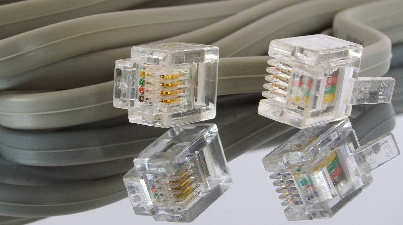
Many modern DCC systems use RJ (Registered Jack) connectors and flat cable. They are used for cab-bus (connecting plug-in panels around the layout) and system-bus (connection between command stations and boosters) DCC system wiring.
These jacks and cables were invented in the 1970s by Bell Labs for the phone industry and have various designations, such as RJ9, RJ11, RJ12. These names can be confusing, but I'll show you a better way to differentiate between them.
RJ11 6P4C telephone wired (inverting) cables
As developed, the connections reversed from one end of the cable to the other. So, the wire connected to pin 1 on one end became connected to pin 6 on the other. This was fine for the phone industry, as their signals are polarity insensitive. Making the cables this way is a touch easier than keeping the polarity constant, making them less expensive.
So, when the information technology industry started using the same hardware, they frequently distributed power on these cables and inverting the polarity could cause malfunctions and irreparable damage. For example NCE DCC systems put +12 volts DC on one wire and the negative (or common) on the opposite wire (for example pins 1 and 6). So, reversing them would short out the power supply. In these uses, the wiring has to be STRAIGHT, also called DATA WIRED.
Telephone and other polarity insensitive applications work just fine with either way of manufacturing. The slightly lower cost has perpetuated the availability of the reversing design.
Later, a similar (larger) jack was used for Ethernet computer connections, It is called RJ45. Some DCC systems use these cables as well as the telephone-based cables. By the time RJ45s came into usage, the issue with the telephone RJ cables was understood and the RJ45 cables don't have the same polarity issues.
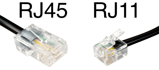
Ethernet (RJ45) vs. telephone RJ11 cables
Since many model railroad hobbyists make their own RJ cables, let's dig a bit deeper into them. DATA cables will work on any DCC system, if they have the right connectors and number of wires. TELEPHONE cables may work on some systems but will not work on all. So, I'm only going to talk about STRAIGHT or DATA WIRED cables.
First consideration is the number of positions in the connectors. The most widely used connector for DCC has 6 positions (places where a wire or contact can exist). A physically smaller connector only has 4 positions. However, the standards don't require that all positions be populated with contacts or wires. So a reference has evolved, where the number of positions and the number of wires and contacts are specified. This is much more descriptive than the RJ11 or whatever designation. Here is the shorthand. A connector is called, for example, a 6P4C if it has 6 possible positions (6P) but only 4 have contacts and wires (4C). A physically smaller connector with two wires would be referred to as 4P2C. Makes more sense to me than trying to remember how many of what an RJ9 is.
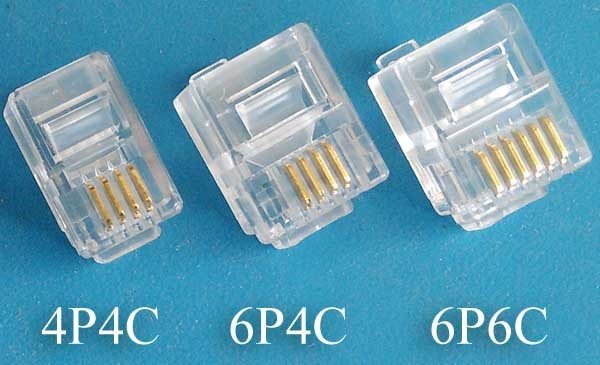
4P4C 6P4C 6P6C connector comparison
So, here is the way to make things simple.
- Do not buy any RJ cables from a home improvement store for your DCC system. There is a 90+% chance that they will be telephone wired.
- If you purchase cables or make your own, only get DATA WIRED cables that are 6P6C or 4P4C. These will work in any situation where the plug will fit into the socket.
Here is how to verify that you have DATA cables. The color of the wires is immaterial. The location in the jack is paramount.
When you look at both ends of the cable with the locking tab in the same direction (either toward you or away from you) on both ends, the same colors need to be on the same sides.
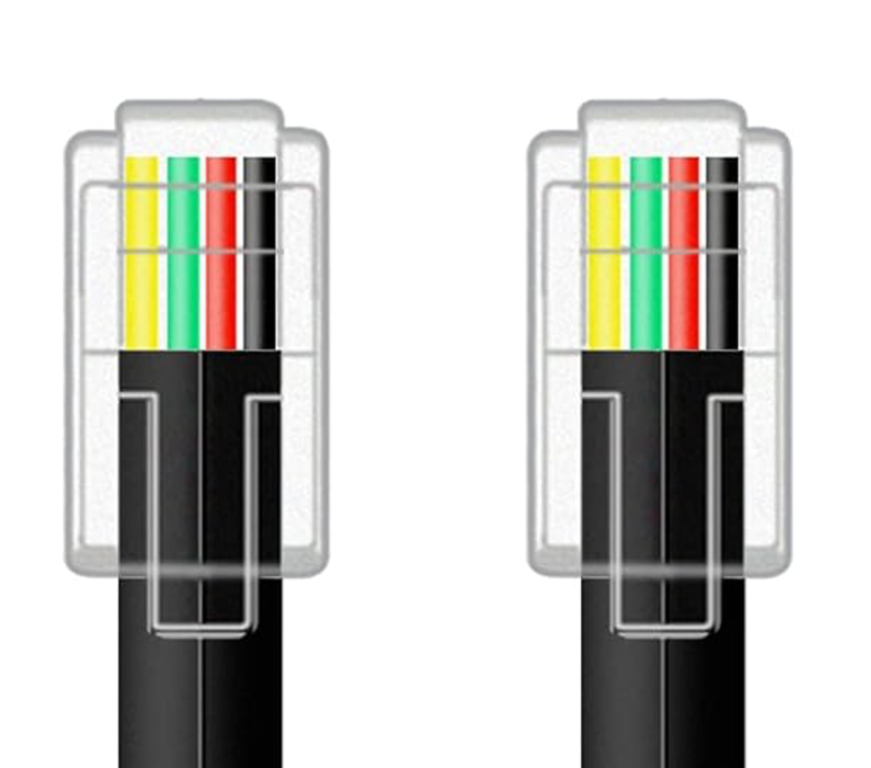
4P4C Data Wired cable
Here are the cables that are most common in the DCC world:
Digitrax LocoNet (combines both system-bus and cab-bus) capabilities and uses 6P6C cables.
NCE cab-bus (connecting cab panels together; NCE-USB adapter to the system box, etc.) uses 6P6C.
NCE system-bus (connects the command station and boosters, such as on the front of a system box) uses 4P4C.
NCE PowerCab connection to the Power Control Panel (PCP) uses 6P6C - FLAT cable provided by NCE. Be very careful with coiled cords. Most are telephone wired and don't have adequate power handling capabilities.
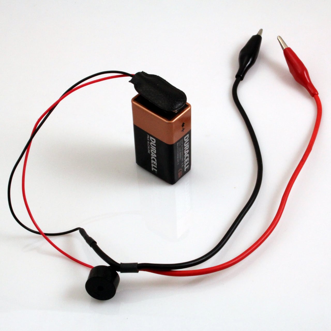
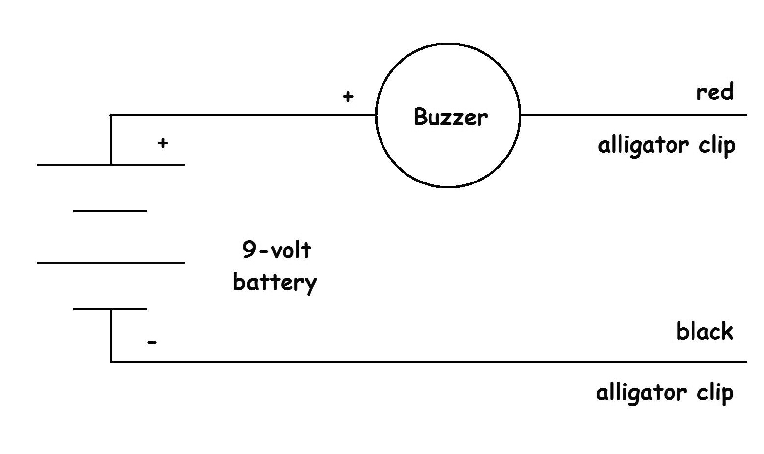
A 9 volt battery and a buzzer (allelectronics.com has them) connected between the two bus wires will buzz the instant you start to wire a short into the layout. The most frequent sources of shorts are “Electro-Frog” switches where the points aren’t insulated and getting confused wiring the track and crossing your wires.
You want to solder a drop to every piece of track. I recommend that, on long stretches of flex track, you solder the rail joiner to both pieces of rail and the drop to that connection.
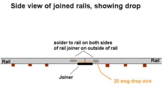
So, at every other rail joiner, drill a hole near the rail on each side. Solder your 20 AWG wire to the rail on each side of the joiner as shown.
Connect the feeders to the DCC bus. Here is an example where I used 14 AWG district bus wire (after the circuit breakers) with color coding shrink tubing and color coded feeder wires on the PebbleCreek Model Railroad Club layout.

Other items to consider
Since DCC is a bit more sensitive to power disruptions than DC, improved reliability can be had by paying a bit more attention to your turnout wiring than you may be used to. Bruce recommends current vintage turnouts, as they are DCC "aware". Older turnouts may need lots of fiddling to handle the momentary shorts. Turnouts basically fall into two categories – here’s a discussion of both and how to handle them:
Peco “Inslu-Frog”, Atlas, and such
These turnouts can be used directly without any need for modification. Advantage: easy to use – Disadvantage: not as easy to set up signals and there is about a one inch dead spot right at the frog (locos with minimal pickup may stall on the switch). I like to drop power to the turnout four places: each of the four rails at the exit of the turnout.
Peco “Electro-Frog”, Shinohara, and such
These turnouts can be used directly by putting insulated joiners on each of the two rails connected to the points of the turnout. There may be some limited reliability, depending upon the contact between the moving point and each rail. To enhance the reliability of these turnouts, use an external switch (part of the ground throw or motor which moves the turnout) and connect power from the selected rail to the frog by an extra drop somewhere inside the triangle. Advantage is that there is almost NO area where the loco does not receive power. Also you can create “quick and dirty” signaling with these turnouts. With a bicolor three lead LED, connect each element to one side of the track. Connect the common lead to the points with a series dropping resistor. Now when the turnout moves the light changes. Power drops to the two outside rails will suffice, especially if you have used an external switch to route power to the frog.
How many operators are you going to have?
Bruce recommends one power district for each JOB! If one job is running a yard, the yard and its lead and the mainline connecting it for a distance should be on the same district. Why the mainline? That protects against a situation where the yard switcher derails on the mainline turnout and a through train is coming!
As you can see, a one-operator layout may not need to be subdivided.
Each power district is wired to its own bus and each district bus is powered from the booster through a circuit protector.
Of course you can use ground throws with DCC.
If you want to activate your turnouts with a motor, either stall (Tortoise) or snap, you can do so in the time proven ways with separate power supplies and fascia (or control panel) switches.
If you want DCC (or computer) control of your turnouts, you will want STATIONARY DECODERS for your turnout. These little boards will control between one and eight turnouts each, depending upon design. Typically, if you have a lot of turnouts in a small area (like a yard) a larger capacity board, such as one to activate eight turnouts, will be more economical - only one brain to push around 8 turnouts!
Stationary decoders frequently draw their power and control signal from the DCC bus. However, Bruce highly recommends that you connect your stationary decoders to a SEPARATE bus which goes directly to your booster. Put the layout on a circuit breaker (or more). That way, if you short out on a section of the layout, you can still control the turnouts!
Bruce built a small (8.5 x 1.25 foot) HO shelf layout for testing and setup. It is an expanded Time Saver with an A/D track added. He used it at Litchfield Station. It can be seen in the photo in this newspaper article.

It has four dual turnout stationary controllers activating eight Peco snap motors. There is a circuit breaker between the DCC input to the layout and the track, but the stationary decoders are connected directly to the DCC input.
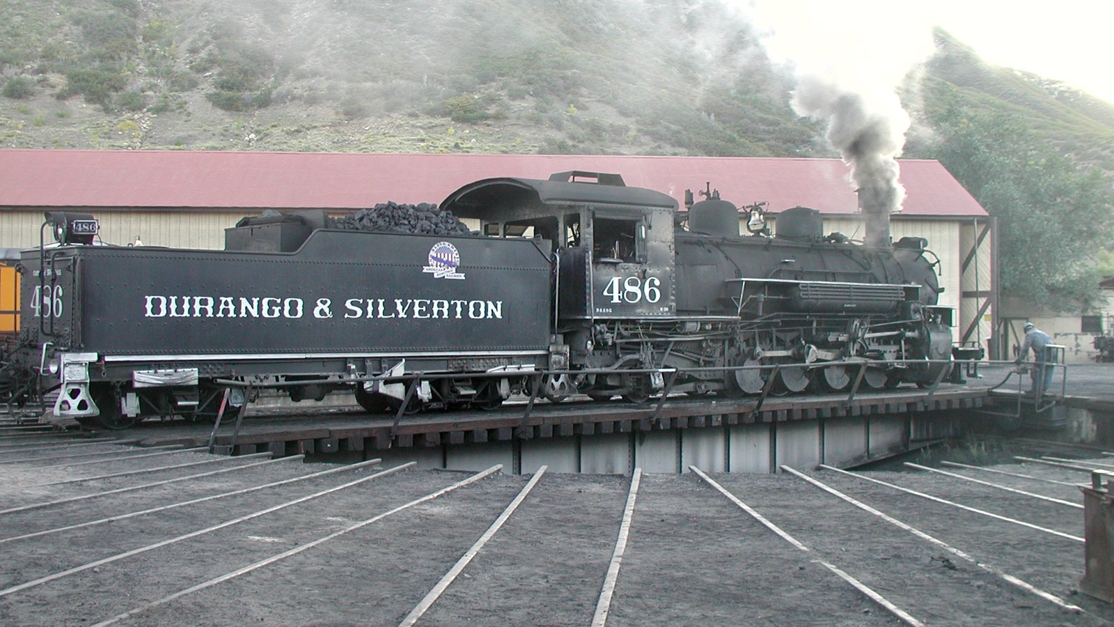
Photo by Bruce Petrarca © Copyright 2003
Turntables come in two types - those with contact rings on the shaft and those that use the shaft to connect one rail and the other rail is connected to the support rail in the pit.
If your model has the track wired with one rail connected to the center post and the other wired to the support rail, you simply connect an autoreverse module between the turntable supply contacts and your DCC bus.
If your turntable has two contacts on the shaft, here is how to tell the difference on your model and how to wire them!
Single Split Ring
Connect your DCC bus to the two contacts directly - the turntable provides the reversing automatically.
Double Continuous Ring
Connect an autoreverse module between the turntable supply contacts and your DCC bus.
Can it really be that simple? Yes, but some folks try to make it hard.