In the "turn of the millennium" time frame, it didn't mean much more than the art department at the manufacturer could spell "DCC". As time has gone by, things have improved.
There can be shorts between the rail power and motor power or lights as part of the internal wiring of the loco. As long as the plug is inserted, this short cannot be identified. Bruce recommends using a BUZZER or ohm meter, probe the gray and black sockets and then the red and orange sockets. There should be high resistance - no buzz. Also probe between the track (black) and light circuits (green, yellow white and blue). Again, no continuity. Finally, probe red rail to lighting.
Here are some data about the connectors in older locomotives.
Today, there are many versions of "DCC Ready" locos in HO scale. Most mean what they say - they are ready for a DCC installation. This doesn't mean that they are ready to RUN on DCC.
Still, they come in various types:
NEM-652 (NMRA Medium) 8-pin socket
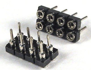
The basic connector, shown below, can be used as a plug (male) or socket (female) connector. It can also be cut down to make 2- or 3- or 4- or 6-pin sockets or plugs.

This socket has connections for the track power, motor and two lights, per the NMRA standard. A third light function (pin 3 - the green wire) as shown below has been implemented by some manufacturers of locos and decoders. There may be some issues with this, as it is NOT an NMRA standard. For example, the Blueline series from BLI will not function correctly with a decoder that implements the green wire function - clipping the green wire off the plug fixes the issue.

This connector is NOT POLARIZED. What that means is that you can plug it into the socket in either direction. The good news is that, except for the green pin discussed above, there will be no damage to either the decoder or the loco if you reverse it. If you plug it in backwards, the lights won't work and the loco will run backwards. Just rotate it a half-turn and plug it in. This "no damage" is not true if you plug it in offset.
JST 9-pin socket
The (usually white) in-line 9-pin plug and socket is used in many locos, for example, the newer Athearn RTR and Genesis locos. The socket (decoder side) of this connection is shown to the left, with the NMRA standard color coding. There is frequently a jumper socket in the loco that makes the connections between the rails and the motor and lights. Once you remove the jumper socket and determine there is no short, as explained above, it is a simple matter of plugging in the JST style decoder of your choice. (Editor note: I use the term socket to designate the female side of the connection, as opposed to calling the fixed side the socket, like the AC power in your home.)

This connector is polarized. It cannot be plugged backward without a lot of force and damage. See the little tabs on this photo. They are offset so that you cannot plug it in backwards. Of course, if you file them off, then you can reverse the plug in the socket!
For this reason Bruce recommends that you use the 9-pin JST style connector whenever possible, for example on the Athearn RTR locos.
There are two types of connectors widely used in N scale today::
NEM-652 (NMRA Medium) 8-pin socket
This socket, as shown above, is used in some N scale locos. Usually it is too large for easy connection. Frequent users are the Walthers' tank switchers and some Con-Cor steamers. Remove the jumper, check for shorts as discussed above and plug the decoder in.
NEM-651 (NMRA Small) 6-pin socket

Frequently used in European locos and becoming more widely used in American locos is the NEM-651 socket and plug, as shown above. Remove the jumper, check for shorts as discussed above and plug the decoder in.
This socket is NOT POLARIZED. Hopefully the mating connector is color coded. If you are using a decoder with the 6-pins on it, consult the manufacturer's literature to find out which direction has the right and left wires.
