One of the GREAT things about DCC is the ability of the decoders to provide eye-popping special effects.
Some decoders are optimized for bulbs, some for LEDs and some allow you to use either. Different decoders provide different effects. Check out the specifications on your decoder before you select the actual light you are going to use.
Some of the effects are:
- Strobes
- Ditch Lights
- Rotating headlights (Mars or Gyro)
- Directional Dimming (Rule 17)
Ready? Let's have some FUN with lights!
LEDs are the preferred method
Bruce prefers to use LEDs with a decoder. Why? Several reasons:
- Color - they are now available in Golden White and Sunny White colors, which are very close the color shown in the photo to the left. Gone are the days of "blue-white" LEDs!
- Life - the life span of a full brightness LED is about 5000 hours - that is 2-1/2 years of 8 hours a day, 5 days a week every week! If you are willing to have only 80% brightness - still VERY bright - the life goes up about ten times to about 25 years.
- Low power - very little power is consumed from your DCC set
- Cool operation - they use very little power, so they don't get hot!
Common sizes are:
- T-1 or 3 mm - HO or N scale headlights
- T-1-3/4 or 5 mm - HO and larger headlights
- SMD (surface mount) frequently 0.06 by 0.03 inches
Z headlights and ditch lights and other effects in larger scales
Common colors are:
- Golden white - orange lens but they look the most like incandescent - okay if the bulb in inside the loco shining on a lens
- Sunny white - slightly bluer than the Golden white, but have a "water clear" lens. Bruce owns an Atlas RS-1 that has a similar installation to the one shown on this site with 5 mm Sunny White LEDs replacing the Atlas light pipes - SPECTACULAR!
- "Bright" white - this is a euphemism for BLUE-WHITE or cool white. They look like fluorescent lights as they come. These can be warmed to you choice with Tamiya Acrylic X-26 Clear Orange paint.
- Colors are available for signaling and other effects: red, green yellow, blue
- Multi colors are available, too: red/green; red/yellow; red/green/yellow - if you are going to use them with a decoder, you need a common anode version.
The answer is very simple, but, if you do it wrong, they won't light or will give you a splendid light show for a few seconds, sometimes taking the driver transistor in the decoder south with them.
Current Limitation
LEDs have a voltage level needed to “fire” them. Below that voltage you get no light. This voltage is related to the way that they generate a particular wavelength of light. A specific color will have a specific voltage, ranging from about 2 volts for red to 4 volts for ultraviolet.
LEDs are current driven devices. THEY MUST HAVE A SERIES RESISTOR! Connecting them directly to a voltage source is a recipe for disaster.
They create light in proportion to the amount of current driven through them. This is NOT a linear relationship. A 10 mA rated device may produce 90% output at 5 mA. The amount of light you desire may come on at only 2 or 3 mA.
Since the output of your decoder is related to track voltage (about 12 to 15 volts), you need a fairly large value of resistance to absorb the extra voltage and limit the current.
Calculating Resistance – The total resistance needed in series with the LED can be calculated easily. I have created a table of total resistance (sum of all resistors in series with a LED) vs. current flow for a white LED, assuming setting of 14 volts out of the booster. Higher track voltage or colored LEDs will increase the current slightly – roughly the amount of changing one resistor size smaller.
|
Resistance In Ohms |
Current in mA |
|
750 |
11 |
|
1000 |
8.5 |
|
1500 |
6 |
|
2100 |
4 |
|
2700 |
3 |
|
4700 |
2 |
As you can see, 1000 or 1500 ohms will get you going with less than 10 mA current. This will probably give enough light for your needs and keep the operating life in the tens of thousands of hours.
Power dissipation will be small enough that 1/8-watt to 1/10-watt resistors will be adequate!
For the theorists in the crowd, here is the formula:
R = E / I = (Track Voltage - LED voltage - Decoder drop) / LED current
If the current value is entered in mA, then the answer is in kilohms. If the current is entered in amps, the answer is in ohms,
Let's calculate the 11 mA number from the above chart, assuming:
14 volt track voltage
4 volt LED firing voltage
1.5 volts Decoder drop: power supply and driver transistor losses
R = (14 - 4 - 1.5) V / 11 mA = 8.5 V / 0.0 11 A = 772 ohms
750 ohms is the closest standard value
While the LED is polarity sensitive, the resistor is not. It can be placed in either direction connected to either lead of the LED. Bruce prefers to put the resistor between the blue lead and the LED, as this provides the greatest margin of safety for the decoder, in the event of a short. The resistor may
If you leave out the resistor, the LED's life is measured in seconds, but the light show is amazing! If the LED fails by shorting out, you will probably toast the transistor in the decoder, too!
Polarity

LEDs are diodes. That means that current only flows in one direction through them. If you hook them up backward, it will probably not damage them, but they will not light.
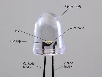
In conventional LEDs, the longest lead as they come from the factory, or the bent lead as shown in this drawing, goes to the positive voltage supply (usually the blue lead).
The other (shorter) lead goes to the function wire (white, yellow, etc.)
With Surface Mount Devices (SMD LEDs) or if you are not sure, the quick way is to connect a 2700-ohm resistor in series with a 9-volt battery. Probe the LED with this connection. When the LED lights, connect the pad that has the positive side of the 9-volt battery connected to it to the blue decoder lead. This test will apply 3 mA or less to any LED. Enough to light but not enough to burn out the most efficient LEDs during a short period of application.
REMEMBER AT LEAST ONE of the leads needs a resistor in it
To light several LEDs with one decoder output, you can wire several identical LEDs in series, up to a point. This is an advanced technique for experienced installers.
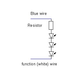
FIRING VOLTAGE - First you must know the firing voltage of your LEDs. If you don't get that data with the LEDs, you can measure it. Connect the 9-volt battery + resistor or buzzer to the LED and get it to light. WHILE IT IS LIT, connect your multi-meter set on the scale that maximizes out at 5 to 20 volts, and read the voltage. That is your LED firing voltage.
SUPPLY VOLTAGE - You can measure the function voltage out of your decoder (blue + and white -) or you can estimate it. If you follow your set manufacturer's instructions to set track voltage or measure it with something like an RRAmpmeter then you know your DCC track voltage. If you subtract 2 from the DCC track voltage you will have a close estimate of the supply voltage.
LED CURRENT - A good place to start is at 75% of the LED rated maximum current. This usually gives enough light and keeps the LED life in the thousands of hours. If you want to fine tune the light level, adjust the brightness of a single LED to the desired value by varying the series resistance and measure the current that results in the desired brightness.
Now you can connect the LEDs in series with a current limiting resistor as shown above, as long as the sum of the firing voltages doesn't exceed the supply voltage.
A good rule of thumb is to assume that white LEDs will require 3 to 3.5 volts to fire and the supply voltage will be 12 volts. Thus, the longest string of LEDs that you could support would be 3.
total LED voltage = 3 LEDs x 3.5 volts = 10.5 volts
which is less than 12 volts
In this case, if you wanted 7.5 mA (0.075 amps) of LED current, the current limiting resistor would be:
Supply Voltage - total LED voltage / LED current in amps
(12 - 10.5) / 0.075 =
1.5 / .075 = 20 ohms
The power consumed would be so little that virtually any wattage resistor would suffice: 1/8 watt discreet or any SMD resistor.
Packaged LEDs include a small die (the actual device) packaged into an epoxy housing with external leads. The longer lead is connected to the anode and should be connected to the positive voltage.
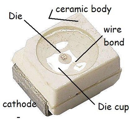
SMD LEDs eliminate the epoxy housing and have the die mounted on a small ceramic holder with connection points on either side.
White LEDs - LEDs emit a small band of frequencies (color) around a center value. White light is the presence of all colors. How do you do this with an LED? The same way you do with fluorescent lights: you make a fluorescent coating that emits the spectrum you want to see and excite it with blue to ultra-violet light from the LED. Varying the chemistry of the coating changes the color mix.
BiColor LEDs – As you can see in the photos above, the die sits in the cathode cup, so the simplest way to have two colors is to put two dies of different color in the same cup. That makes the cathodes common. Well, since our decoders operate by connecting the cathode to the negative voltage, this version won’t work. There are a few folks who make common anode LEDs. If you want a two-color version, you need to find one of these common anode units, or make your own by connecting the anodes of two SMD LEDs of different colors.
LEDs will probably not hurt you. But how do you keep from hurting them?
Connected to a decoder
If you are working with them on the function outputs of a DCC decoder, static electricity and current limitation (discussed above) are the only issues to seriously consider.
STATIC ELECTRICITY - all semiconductor devices, LEDs are one, are sensitive to static electricity. LEDs are fairly immune. It doesn't hurt to touch something metal and grounded before you work with LEDs. Also, do not wear a wool sweater!
Connected to the rails
If you are connecting LEDs to the rails, as with signals or lighting (buildings or cars) , there are other issues to think about.
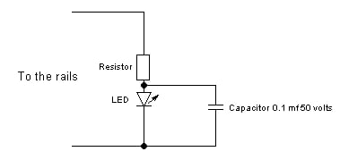
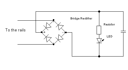
STATIC ELECTRICITY - since the LED may be subjected to static electricity stresses every time someone touches the rails, prudence would include use of a capacitor across the LED do absorb the voltage spike. The circuit shown here will suffice.
If you want to reduce or eliminate flicker, an electrolytic capacitor can be connected in parallel with the 0.1mF capacitor (positive to the junction with the LED and resistor). I'd start with 100 mF.
REVERSE VOLTAGE - LEDs are not designed to be rectifiers. They have limited and usually unspecified reverse voltage ratings. For the greatest safety when connecting them to rails or something where there may be static electricity and alternating current, use a rectifier (bridge is best) with them.
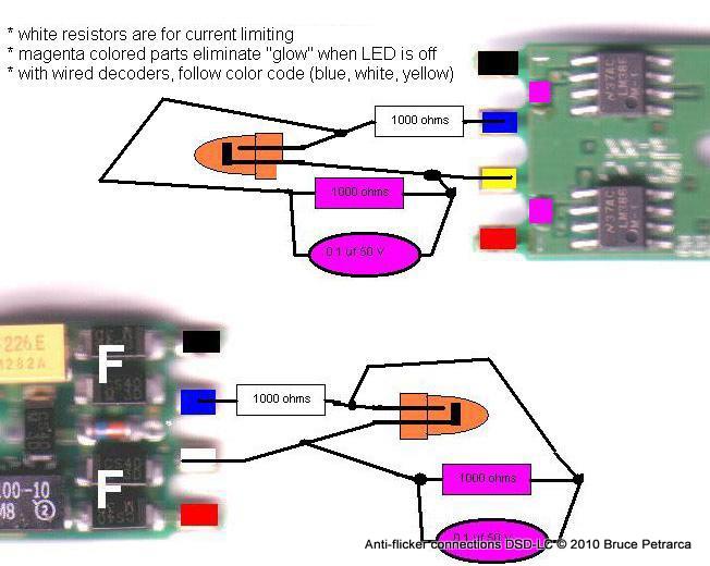
SoundTraxx says that the LC series decoders are not recommended for use with LEDs. Here's why. The design of the decoder has a small amount of current being routed to the lighting circuits during the generation of certain sounds. If incandescent bulbs are used, these pulses of current are not enough to illuminate the bulbs. However, LEDs respond very rapidly and will show a small glow from time to time. There is nothing about this that is incorrect, just a bit less than totally esthetic.
There are two ways to deal with this:
1) Live with it - many folks don't even notice or
2) Fix it - add a resistor and capacitor in parallel with the LED as shown in the drawing below (the magenta colored components). While the drawing below shows the DSD-AT100LC board (the most cryptic as to colors), the basic connection is the same for all LC series decoders, just follow the color code! In this drawing, the component values are a bit hard to read. The resistors are all 1000 (1K) ohms 1/8 watt and the capacitors are 0.1 uF at any voltage larger than 10 volts. Click on the photo to enlarge.
In my Model Railroad Hobbyist article of March 2012, I posted the following:
LEDs are current-based devices. The light they generate depends on the current passing through them. They are NOT a linear device. An LED rated for 10 mA may produce 90% of its light at 5 mA. The amount of light you desire may be produced at 2 or 3 mA. Control the current by placing a resistor in series with EVERY LED! See above on how to select resistor values.
LEDs are diodes. That means that current only flows through them in
one direction. If you hook one up backward, it probably won’t be damaged, but it is not going to light up.
LEDs don’t have large reverse voltage ratings. Don’t use an LED as a rectifier.
Although the light produced by an LED depends on the current, an LED will not start conducting current and producing light until a certain voltage (called the “firing” voltage) is reached. Less voltage than that and you get no light. More voltage and they quickly go over-current and fail. Each color has its own firing voltage ranging from about 2 volts for red to about 4 volts for ultraviolet. White LEDs usually need about 3 volts but that can vary, based on their design.
Don’t connect LEDs in parallel. The firing voltage varies slightly between even supposedly identical devices. Placing multiple LEDs in parallel using a single current limiting resistor is a bad idea.
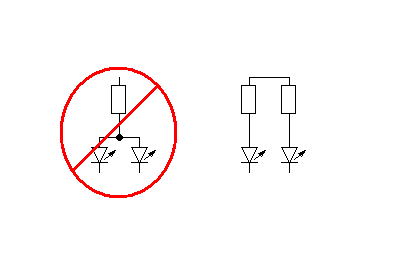
The LED with the lowest firing voltage in the group will hog most of the current. Some LEDs with higher firing voltages may not even fire. Excess current will shorten the life of the lowest voltage LED. When it burns out (assuming it does not short in the process) the next lowest LED takes an even larger amount of current. You get the idea.
LEDs emit a narrow band of wavelengths (color). Because white is a collection of all colors, a single wavelength device can never be white. Instead, the single-wavelength LED die is coated with a fluorescent material. When the LED shines on it, the coating lights up like a fluorescent lamp. The chemical makeup of the coating determines the color emitted. The composition of the coating and the wavelength of the impinging light work together to set the color value.
Since the firing voltage relates to the wavelength, white LEDs may operate anywhere from 2.8 to 4 volts.
Another take
A fellow installer with 27 years in the optoelectronics business, Scott Russell of CR&S Trains, contributed the following insight into LEDs:
The critical parameter to the longevity of an LED is power dissipation as it relates to junction temperature (of the semiconductor junction that is responsible for turning some of the electrons passing through it into photons). Once the junction temperature gets above a safe level, the LED begins to degrade, both in output and wavelength drift. An LED turns about 15% of the input energy into light and 85% into heat. This is a typical value, as it can vary by the efficiency of the material and doping used to produce a particular color.
Obviously, when the LED goes "poof" and you see a little black dot inside, the junction temperature has been greatly exceeded, even if briefly.
The ability of the LED to dissipate heat from the junction is dependent on package design. When LED's (especially IR-LEDs) came in metal packages (that shows my age), the DC forward currents could be as much as 50mA to 100mA. This is why the SMD packages usually have a lower maximum current, since there is nowhere for the heat to go.
Controlling junction temperature is how TV and other remote controls can output energy (usually IR) over great distances. You can drive an LED at 1A or more if it's with a short duty cycle where the LED is on for about 5% of the cycle and off for 95% so the junction can cool. How much pulse current can be handled is also dependent on the gauge of the bond wire used inside the LED to bond the chip to the lead frame (but that's another boring subject, and not relevant here).
That's a long-winded way to get to the point that 1K resistors almost always work, but with more efficient LED's (like the white ones), the extra light generated after 2-5mA may be negligible and the extra current only serves to shorten the LED's life. It may still outlive you, so it may not really matter.
Using 1.5 volt bulbs with DCC decoders
Normally, decoders put out basically track voltage (usually 12 to 16 volts in the HO world) on the function leads. If you connect 1.5 volt bulbs directly to these outputs, their life is measured in a fraction of a second, perhaps even destroying the control transistor inside the decoder. There are several ways to control these lovely bulbs, each with advantages and disadvantages!
BEWARE: most folks apply more than 1.5 volts to these bulbs. When they have the correct amount of voltage and current, they are not very bright and only last a few hundred hours. If you apply MORE voltage, they will draw more current than they are rated for and reduce their life significantly!
Consider an alternative to these small bulbs: surface mount LEDs. They are MUCH brighter than the 1.5 volt bulbs and measure their life in thousands of hours and are easy to tame. If you put about 2000 ohms in series with a surface mount LED, you will get a result that is at least as bright as a 1.5 volt bulb and easily 20,000 hours of life - that means that the LED will burn for TEN YEARS of 8 hours a day, five days a week! Drop the resistor to about 750 ohms and the brightness will blow you away and the service life will only be a couple of years of 8 hours a day, five days a week.
How much work is it to change the bulb you are connecting?
Still want to use 1.5 volt bulbs? Here are some ways:
Manufacturers are starting to make decoders with 1.5 volt support included. This is the easy way to tackle these little bulbs!
The TCS A6X HO decoder was the first. It is built on an Atlas Light Board sized circuit board. It can control up to 6 functions with an internal 1.5 volt regulator, providing 100 mA of current - enough for 6 standard 1.5 volt bulbs drawing 15 mA each .
The SoundTraxx TSU-AT1000 diesel Tsunami is built on an Atlas Light Board sized circuit board. It can control up to 4 functions with an internal 1.5 volt regulator, providing 150 mA of current - enough for 10 standard 1.5 volt bulbs.
Train Control Systems also offers an external 1.5 volt regulator to interface with some of their other decoders.
If you know your track voltage and will NEVER operate your loco on another layout or change the track voltage on your layout, then you can simply add a resistor in series with each 1.5 volt bulb. The formula for calculating the resistor is:
Resistor (ohms) = 1000 * (track voltage - 1.5) / (bulb current in mA)
For a 15 mA bulb with 15 volts on the track, the value is:
Resistor (ohms) = 1000 * (15-1.5)/15 = 900 ohms - since 910 ohms is a standard value, select that. If you want to have a longer bulb life, increase the resistor a tad to 1000 (1K) ohms.
The advantage of this method is that it is quick and cheap. You MUST know the current draw of the bulb. The disadvantage is that the bulb(s) may vary from not lit to blown out depending upon the design voltage and the track voltage as you move from one layout to another. Also, there is a tendency to reduce the resistor value to get a bit more brightness out of the bulbs, reducing the bulb's life
The quickest and cheapest and most reliable system is to add a couple of diodes to the basic conneciton above to regulate the voltage applied to the bulb(s). A forward biased (activated) diode drops about 0.7 volts, so two in series will provide about 1.4 volts over a wide range of input voltages.
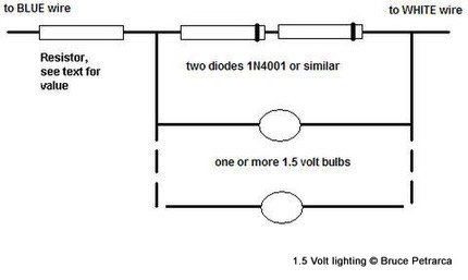
In the above circuit, it is critical that the banded end of the diodes are connected as shown. The BLUE connection can be to the blue wire or to a rail (red or black). The WHITE connection can be any function lead (yellow, green, brown, etc.).
For 15 mA bulbs, the resistor will vary with the number of bulbs as shown below. These values are calculated for any track voltage between 12 and 16 volts:
|
Bulbs |
Ohms |
Watts |
|
1 |
240 |
1/2 |
|
2 |
150 |
1/2 |
|
3 |
100 |
1/2 |
The advantage of this scheme is that it is easy and inexpensive and provides good performance over a wide range of track voltages. The disadvantage is that the resistor can get rather warm and should not be in contact with plastic components.
A solid state current regulator can be used to contol as many 15 mA bulbs as you wish to light at one time (up to about 6). A LM334 Integrated Circuit can be connected with a 5.1 ohm resistor to make a current limiter that will deliver about 14 mA regardless of the supply voltage. This elegant solution runs very cool and is small, allowing for easy installations. Connect the IC as shown in the diagram below and cover with shrink tubing.
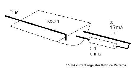
The single lead can be connected to the decoder blue wire or a rail (red or black) wire. The other end of the bulb (or string of bulbs in series) is connected to the function lead (white, yellow, etc.).
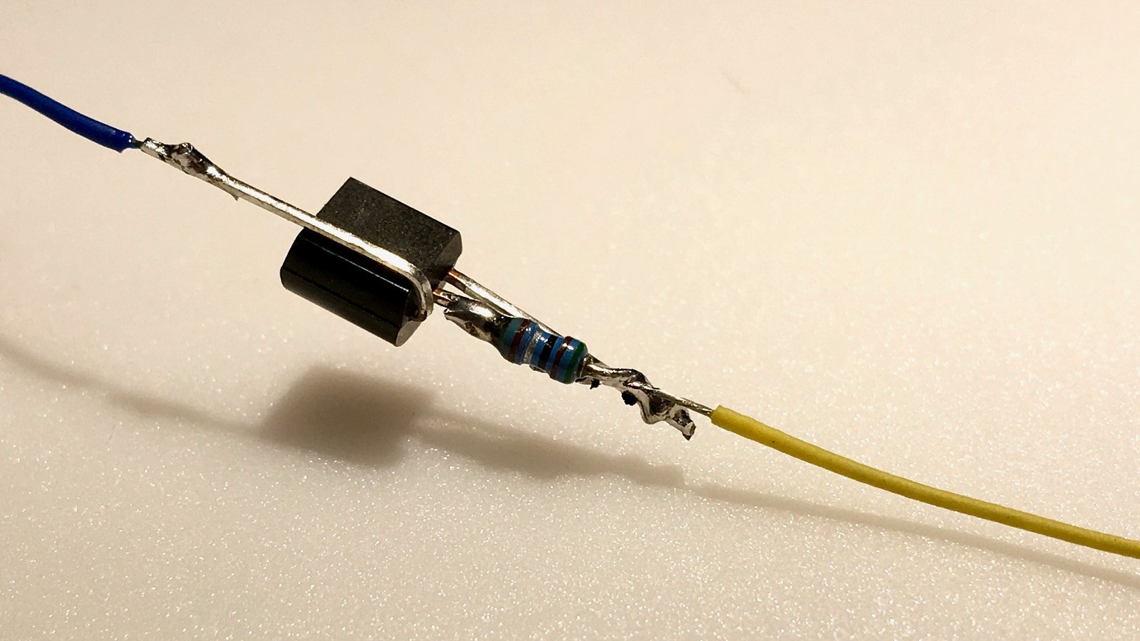
A photo is sometimes worth 1000 words. Here is one that I built just before I put heat-shrink tubing over it (I used ⅜ inch diameter tubing).
Folks have noted that this circuit is outside the range specified for the LM334. I’ve built and used these circuits for at least 10 years with no failures.
An alternative method is shown below. It will provide 1.25 volts to as many bulbs as you choose to attach in parallel.

Here is a photo of a 15 mA bulb being driven by the circuit chown above. The red wire in the photo would be the blue wire coming from a decoder and the black wire in the photo would correspond to a function wire, say the white or yellow.

Using track voltage bulbs with DCC decoders
The bulbs were connected directly to the track and worked on this loco on DC, why should I not just connect them to the decoder's "track voltage" output?
To get some light out of the bulb at less than full speed, the manufacturers use 12 volt (or sometimes even less) bulbs. When you connect these to the (frequently as high as 15 volt) outputs from your decoder, their life is severly limited.
Bruce recommends LEDs as the primary replacement for bulbs.
If you insist on keeping bulbs in your loco, there are two things that you can do to prolong the life of the bulb and the decoder.
BEWARE that track voltage bulbs and the series resistors get VERY HOT.
They may melt plastic shells or detail parts.
- Put a 22 ohm 1/4 watt resistor in series with the bulb. This does two things! Firstly, it limits the inrush current to the bulb when it is turned on cold, protecting the decoder. Secondly, it SLIGHTLY reduces the voltage on the bulb, prolonging its life. The resistor will get HOT - keep it away from plastic shells!
- Change the bulb out for a 14 volt bulb and STILL USE the 22 ohm resistor. Being closer to the voltage coming out of the decoder, they will have a much longer life than the original bulbs.
